Annex
ANNEX
REGULATION ON
SUBDIVISION AND STABILITY OF PASSENGER SHIPS AS AN EQUIVALENT TO PART B OF
CHAPTER II OF THE INTERNATIONAL CONVENTION FOR THE SAFETY OF LIFE AT
SEA,1960
1. The Regulations
hereunder constitute an equivalent to and a total alternative to the
requirements of Part B of Chapter II of the International Convention for the
Safety of Life at Sea, 1960 for Passenger ships,
2. In applying these equivalent Regulations the following
should be observed for other Parts of Chapter II of that Convention: PART A
-Regulation 1(d)and Regulation 2 are not applicable. PARTS C, F AND H - In
Regulations 25(a), 37(b), 68(a), 94(1), 96(b), 99(a),(b)and(c)and 108 the
term "bulkhead deck" is to be replaced by the term "relevant bulkhead deck"
as defined in Regulation 1(e) of the equivalent Regulations.
3. The following references to Regulations relate
solely to the Regulations of this Equivalent.
Regulation 01 Definitions
For the purpose of these Regulations, unless
expressly provided otherwise:
(a)(I) A "subdivision loadline" is a waterline used in
determining the subdivision of the ship; and
(II) the
"deepest subdivision loadline" is the waterline which corresponds to the
greatest draught permitted by the subdivision requirements which are
applicable.
(b) the "subdivision length of the ship" (L
s) is the
extreme moulded length of that part of the ship below the immersion
limit line.
(c) "midlength" is the midpoint of the subdivision length of the
ship (L
s).
(d)(I) the "breadth" (B
1) is the extreme moulded
breadth of the ship at midlength at or below the deepest subdivision
loadline;
(II) the "breadth" (B
2) is
the extreme moulded breadth of the ship at midlength at the relevant
bulkhead deck.
(e) The "relevant bulkhead deck" is the uppermost deck which,
together with the watertight bulkheads bounding the extent of flooding
under consideration and the shell of the ship, defines the limit of
watertight integrity in the flooded condition.
(f) The "immersion limit line" at any point in L
s is
defined by the highest relevant bulkhead deck at side at that point.
(g) The "draught" (d
i) is the vertical distance from
the moulded base line at midlength to the waterline in question.
(I) The "subdivision draught" (d
s) is the
draught up to the subdivision loadline in question.
(II) The "lightest service draught" (d
o) is the service
draught corresponding to the lightest anticipated loading and associated
tankage, including, however, such ballast as may be necessary for
stability and/or immersion.
(III) Intermedaite
draughts between ds and do are:
 (h)
(h) The "effective mean damage freeboard" (F
1) is
equal to the projected area of that part of the ship taken in the
upright position between the relevant bulkhead deck and the damage
waterline and between 1/3 L
s forward and abaft the midlength
divided by 2/3 L
s . In making this calculation no part of the
area which is more than 0.2B
2 above the damage waterline
shall be included. However, if there are stairways or other openings in
the bulkhead deck through which serious downflooding could occur F1
shall be taken as not more than 1/3 (B
2 tan g
Øf ), where
Øf is the angle
at which such openings would be immersed.
(i) The "permeability" (µ) of a space is the proportion of the
immersed volume of that space which can be occupied by water.
Regulation 02 Subdivision Index
(a) To provide for buoyancy and stability
after collision or other damage, ships shall have sufficient intact
stability and be as efficiently subdivided as is possible having regard
to the nature of the service for which they are intended.
(b) The subdivision of a ship is considered sufficient if:
(I) the stability of the ship in damaged condition
meets the requirements of Regulation 5; and
(II) the
attained Subdivision Index A according to Regulations 6 and 7 is not
less than the required Subdivision Index R calculated in accordance with
paragraph (c) of this Regulation.
(c) The degree of subdivision is determined by the required
Subdivision Index R, as follows:

Where:
N
= N
1 + 2N
2
N
1 = number of persons for whom life-boats are
provided.
N
2 = number
of persons (including officers and crew) that the ship is permitted to
carry in excess of N
1(d) Where the conditions of service are such that compliance with
paragraph (b) of this Regulation on the basis of N = N
1 +
2N
2 is impracticable and where the Administration
considers that suitably reduced degree of hazard exists, a lesser value
of N may be taken but in no case less that N = N
1 +
2N
2.
Regulation 03 Special Rules concerning Subdivision
(a) In ships 330 feet (or 100 metres) in
length and upwards the watertight transverse bulkhead next abaft the
forepeak bulkhead shall be located so that the s-value, as defined in
Regulation 6(a), for a combination of the forepeak and adjacent
compartment, calculated by formulae (VIII) and (IX) shall not be less
than 1.0. However, in no case shall the distance between the forepeak
bulkhead and the next bulkhead be less than the longitudinal extent of
damage specified in Regulation 5(b)(i).
(b) A watertight transverse bulkhead may be recessed provided
that all parts of the recess lie inboard of vertical surfaces on both
sides of the ship, situated at a distance of 0.2 B1 from the
ship's side, and measured at right angles to the centreline at the level
of the subdivision loadline. Any part of a recess which lies outside
these limits shall be dealt with as a step, as provided in Regulation
5(b)(i).
Regulation 04 Permeability
(a) For the purpose of the
subdivision and damage stability calculations of Regulation 5 ,6 and 7
the permeability of each space or part of a space subject to flooding
either during any intermediate stage or in the final stage of flooding
shall be as follows:
 (b)
(b) The permeability of any space appropriated for cargo shall be
assumed to vary with the draught before damage in such a way that for
any initial draught d i the permeability i of any cargo space shall be
taken as:

but not more than 0.95 nor
less than 0.60.
(c) If the ship's arrangement or service are such that the use of
other permeabilities resulting in more severe requirements is logical
the use of other permeabilities may be required by the
Administration.
Regulation 05 Subvision and Damage Stability
(a) Sufficient intact stability shall be
provided in all serveice conditions so as to enable the ship to comply
with the provisions of this Regulation. Before certification of the ship
the Administration shall be satisfied that the required intact stability
can praticably be obtained in service.
(b)(I) All ships shall be so designed as to comply with the
provisions of this Regulation in the event of flooding due to one side
damage with a penetration of 0. 2B1 from the ship's side at
right angles to the centreline at the level of the subdivision loadline
and a longitudinal extent of 9.8 feet (3.00 metres) + 0.03 Ls
, or 36 feet (11 metres) whichever is the less, occurring anywhere in
the ship's length, but not including a transverse bulkhead. However,
where a bulkhead is stepped it shall be assumed as subject to damage.
(II) Ships for which N is more that 600 shall
additionally be able to comply with this Regulation in the event of
flooding, due to side damage including transverse bulkheads occurring
anywhere within a length equal to ( N/600- 1. 00)
Ls , measured from the forward terminal of Ls
, where N is as defined in Regulation 2(c) and (d).
The value of ( N/600- 1. 00) shall not be more
than one.
(III) In any calculation required under this
paragraph the damage shall be assumed to extend from the base line
upwards without limit. However, if flooding due to a lesser extent of
damage either vertically, transversely or longitudinally results in a
higher necessary intact metacentric hieght, such a lesser extent of
damage shall be assumed. In all cases, however, only one breach in the
hull and only one free surface need be assumed. For the purpose of
assessing heel prior to equalization the bulkheads and deck bounding
refrigerated spaces and other decks or inner divisions which in the
opinion of the Administration are likely to remain sufficiently
watertight after damage, shall be regarded as limiting flooding.
Otherwise, flooding shall be assumed as limited only by undamaged
watertight structural divisions.
(c)(I) In the final stage of flooding:
(1)
there shall be a positive metacentric height, GM, calculated by the
constant displacement method and for the ship in upright condition, of
at least (2) the angle of heel in the case of one compartment flooding
shall not exceed 7 degrees. For the simultaneous flooding of two or more
adjacent compartments a heel of 12 degrees may be permitted unless the
Administration considers a lesser heel necessary to ensure an adequate
amount and range of residual stability; (3) except in way of the flooded
compartment or compartments no part of the relevant bulkhead deck at
side shall be immersed.
(II) Unsymmetrical flooding
shall be kept to a minimum consistent with efficient arrangements. If
any equalizing arrangements are necessary to ensure that the angle of
heel in the final stage of flooding does not exceed the limits specified
in sub-paragraphs (i)(2) and (3) of this paragraph, these arrangements
shall, where practicable, be self-acting. However, if controls are
necessary, they shall be operable from above the highest relevant
bulkhead deck. All such arrangements shall be acceptable to the
Administration.
(III) The Administration shall be
satisfied that stability prior to equalization is sufficient. However,
in no case shall the maximum heel before equalization exceed 20 degrees
nor shall it result in progressive flooding. Additionally, the time for
equalization of cross-connected spaces to at least the limits specified
in sub-paragraphs (i)(2) and (3) of this paragraph shall not exceed ten
minutes.
(IV) The Administration shall be
satisfied that the residual stability is sufficient during intermediate
flooding and that progressive flooding will not take place. Calculations
relative thereto shall be in accordance with the provisions of
sub-paragraph (b)(iii) of this Regulation, respecting the assumed extent
of damage and resulting extent of flooding. Heel during intermediate
flooding due either to negative metacentric height alone or in
combination with unsymmetrical flooding shall not exceed 20 degrees.
(d) Damage stability calculations performed in compliance with
this Regulation shall be such as to take account of the form and the
design characteristics of the ship and the arrangements, configuration
and probable contents of the compartments considered to be flooded. In
making calculations for heel prior to equalization and for equalization
time, the flooding of that portion of the ship opened to the sea shall
be assumed to be completed prior to commencement of equalization. For
each initial draught condition the ship shall be at the most
unfavourable intact service trim anticipated at that draught having
regard to the influence of the trim on the freeboard in the flooded
condition.
(e) The intact metacentric height, and corresponding vertical
centre of gravity, necessary to provide compliance with the requirements
specified in paragraphs (b) and (c) of this Regulation shall be
determined for the operating range of draughts between ds and
do. If ( ds-do) does not exceed 0.1
ds , damage stability calculations may be made only for d
sand do, and the intermediate values may be obtained by
linear interpolation. If ( ds-do)exceeds 0.1
ds , damage stability calculations shall also be made for
at least one additional intermediate draught. However, in all cases
where there are vertical discontinuities in permeabilities or in free
surfaces which may result in discontinuities in the necessary intact
metacentric height, damage stability calculations shall be made for the
corresponding draughts in order to define such discontinuities.
Regulation 06 Attained Subdivision Index A
(a) (I) In addition to complying with
Regulation 5 the attained Subdivision Index A shall be determined for
the ship by formula (II):

Where:
"a" accounts for the
probability of damage as related to the position of the compartment in
the ship's length,
"p" evaluates the effect of the
variation in longitudinal extent of damage on the probability that only
the compartment or group of compartments under consideration may be
flooded, and
"s" evaluates the effect of freeboard,
stability and heel in the final flooded condition for the compartment or
group of compartments under consideration.
(II) The
summation indicated by formula (II) is taken over the ship's length for
each compartment taken singly. To the extent that the related buoyancy
and stability in the final condition of flooding are such that "s" is
more than zero, the summation is also taken for all possible pairs of
adjacent compartments, and may be taken for all possible groups of a
higher number of adjacent compartments if it is found that such
inclusion contributes to the value of the attained Subdivision Index
A.
(III) Wherever wing compartments are fitted and
where the assumed damage used in the damage stability calculations
according to Regulation 5 forming the basis for the "s" calculation does
not result in flooding of the associated inboard spaces, "p" shall be
multiplied by "r" as determined in Regulation 7(b).
(b) The factor "a" in formula (II) shall be determined for each
compartment and for each group of compartments by formula (III):


For the purposes of this
paragraph and of paragraph (c) of this Regulation, with respect to the
length of any compartment or groups of compartments under consideration,
where one or both of the limiting bulkheads have steps, the forward and
after ends of the considered compartment or group of compartments shall
be taken at the portions of the bulkheads which are nearest to each
other.
(c) The factor "p" in formula (II) shall be determined for each
compartment and for each group of compartments by formulae (IV) -
(VII).
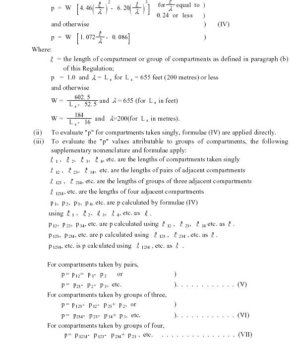 (d)
(d) The factor "s" in formula (II) shall be determined for the
final stage of flooding for each compartment and for each group of
compartments by formulae (VIII) and (IX). (i) In general, for any
condition of flooding from any initial draught di, si shall be:


but not more than 1.0.
Where:

GM
R = the
highest required intact metacentric height at the relative draught, as
determined in Regulation 5(e) or if a higher metacentric height is to be
specified in the instructions to the Master, that value may be used;
MM
S = the reduction in the height of the
metacentre as a result of flooding, calculated for the ship in the
upright position in the final stage of flooding.


Values of GM
R
for the draughts d
1, d
2 and d
3 are
determined from the plot of GM
R versus draught to be
furnished to the Master of the ship in accordance with Regulation 8.
Values of MM
S and F
1 for these draughts are
determined from plots of damaged condition vertical metacentre, trim,
draught and heel versus undamaged draught, determined in accordance with
Regulation 5(e).
(iii) Provided a positive
contribution to the attained Subdivision Index A is obtained thereby,
the flooding of combinations of adjacent compartments in excess of those
required for compliance with Regulation 5(b)(i) and (ii) may be included
in the calculations. However, s i shall be taken as zero for any case of
flooding which results
(1) during intermediate
flooding or prior to equalization in an angle of heel in excess of 20
degrees or which immerses any opening through which downflooding might
take place, or
(2) for the final stage of flooding,
except in way of the flooded compartment or compartments, in immersion
of the relevant bulkhead deck at side, or heel in excess of 12 degrees,
or (GM
R - MM
S ) less than 2 inches (0.05
metre).
Regulation 07 Combined Longitudinal and Transverse Subdivision
Regulation 7
Combined Longitudinal and Transverse
Subdivision
(a) Regulation 6 is predicated upon the condition that transverse
bulkheads ordinarily extend from side to side. However, an
Administration may also accept a combination of transverse and
longitudinal watertight bulkheads wherein some of the transverse
watertight bulkheads extend inboard only to longitudinal watertight
bulkheads, provided that:
(I) A horizontal watertight
division located not less than 0.1B
1 above the base line is
fitted in the centre space between the longitudinal bulkheads, and the
space below the horizontal division is subdivided by watertight
bulkheads in line with the watertight transverse bulkheads in the wings
or by equivalent means.
(II) Compliance with the
provisions of Regulation 5 is demonstrated.
(III) The
Subdivision Index A, calculated according to paragraphs (b) and (c) of
this Regulation is not less than the required Subdivision Index R.
(b) To calculate the contribution of the wing compartments to the
attained Subdivision Index A:
(I) "a" is calculated as
in Regulation 6(b) using the distances from the aft terminal of Lsto the
transverse bulkheads bounding the considered wing compartment or group
of compartments.
(II) "p" is obtained by multiplying
the values obtained by application of formulae (IV) of Regulation 6(c)
by the reduction factor "r" according to formulae (X), which represents
the probability that the inboard spaces will not be flooded.

 (c)
(c) If the attained Subdivision Index A obtained by application
of the procedures in paragraph
(b) of this Regulation
is less than the required Subdivision Index R, the additional
contribution to the attained Subdivision Index A attributable to
flooding of spaces inboard of the longitudinal bulkheads together with
the outboard spaces may be included. For the purpose of this
contribution:
(I) "a" is calculated as in
sub-paragraph (b)(i) of this Regulation except that the distances from
the aft terminal of L
s are taken to each transverse bulkhead
bounding either a wing or an inboard compartment or group thereof.
(II) "p" is obtained by multiplying the values
obtained by application of formulae (IV) through (VII) of Regulation
6(c) by (1 - r).
(III) "s" is calculated as in
Regulation 6(d). In so doing, the assumed extent of flooding of both
wing and inboard spaces shall be that which would result from an assumed
longitudinal extent of damage coincidental with the longitudinal limits
used in calculating "a" and "p" and extending in to the ship's
centreline.
Regulation 08 Stability Information
(a) (I) Every passenger ship shall be
inclined upon its completion and the elements of its stability
determined.
(II) Where any alterations are made to
a ship so as to materially affect the stability information supplied to
the Master, amended stability information shall be provided. If
necessary the ship shall be reinclined.
(b) The Master of the ship shall be supplied with such reliable
information as is necessary to enable him by rapid and simple means to
obtain accurate guidance as to the stability of the ship under varying
conditions of service which information shall include:
(I) a curve of minimum operational metacentric
height versus draught which assures compliance with the requirements of
Regulations 5, 6 and 7, as well as a corresponding curve of the maximum
allowable vertical centre of gravity versus draught, or with the tabular
equivalents of these curves;
(II) tables containing
draught limits and their corresponding trim limits within which the
requirements of Regulations 5, 6 and 7 can be met;
(III) instructions concerning the operation of cross-flooding
arrangements; and
(IV) all other data and aids which
might be necessary to maintain the required stability after damage.
(c) There shall be permanently exhibited, for the guidance of the
officer in charge of the ship, plans showing clearly for each deck and
hold the boundaries of the watertight compartments, the opening therein
with the means of closure and position of any controls thereof, and the
arrangements for the correction of any list due to flooding. In
addition, booklets containing the aforementioned information shall be
made available to the officers of the ship.
(d) All information called for by this Regulation shall be
subject to approval by the Administration.
Regulation 09 Ballasting
When ballasting with water is necessary, the water
ballast should not in general be carried in tanks intended for oil fuel.
In ships in which it is not practicable to avoid putting water in oil
fuel tanks, oily-water separator equipment to the satisfaction of the
Administration shall be fitted, or other alternative means acceptable to
the Administration shall be provided for disposing of the oily-water
ballast.
Regulation 10 Peak and Machinery Space Bulkheads, Shaft Tunnels, etc
(a) (I) A ship shall have a forepeak or
collision bulkhead, which shall be watertight up to the relevant
bulkhead deck. This bulkhead shall be fitted not less than 0.05
Ls and not more that 9.8 feet (or 3.0 metres) + 0.05
Ls abaft the forward terminal of the deepest subdivision
loadline.
(II) If a ship has a long forward
superstructure and the residual freeboard at the forward terminal of
Ls after flooding of the foremost compartment is less
than the summer freeboard required amidships according to the
International Convention on Load Lines, 1966 the collision bulkhead
shall be extended weathertight to the deck next above the relevant
bulkhead deck. The extension need not be fitted directly over the
bulkhead below, provided it is at least 0.05 Ls abaft the
forward terminal of the deepest subdivision loadline and the part of the
relevant bulkhead deck which forms the step is made effectively
weathertight.
(b) An after peak bulkhead and bulkheads dividing the machinery
space from the cargo and passenger spaces forward and aft shall also be
fitted and made watertight up to the relevant bulkhead deck. The
afterpeak bulkhead may, however, be stepped below the relevant bulkhead
deck, provided the degree of safety of the ship as regards subdivision
is not thereby diminished.
(c) In all cases stern tubes shall be enclosed in watertight
spaces of moderate volume. The stern gland shall be situated in a
watertight shaft tunnel or other watertight space separate from the
stern tube compartment and of such volume that, if flooded by leakage
through the stern gland, the relevant bulkhead deck will not be
submerged.
Regulation 11 Double Bottoms
(a) A double bottom shall be fitted extending
from the forepeak bulkhead to the afterpeak bulkhead as far as this is
practicable and compatible with the design and proper working of the
ship.
(I) In ships 165 feet (or 50 metres) and
under 200 feet (or 61 metres) in length a double bottom shall be fitted
at least from the machinery space to the forepeak bulkhead, or as near
thereto as practicable.
(II) In ships 200 feet (or 61
metres) and under 249 feet (or 76 metres) in length a double bottom
shall be fitted at least outside the machinery space, and shall extend
to the fore and after peak bulkheads, or as near thereto as
practicable.
(III) In ships 249 feet (or 76 metre)
in length and upwards a double bottom shall be fitted amidships, and
shall extend to the fore and after peak bulkheads, or as near thereto as
practicable.
(b) Where a double bottom is required to be fitted its depth
shall be to the satisfaction of the Administration and the inner bottom
shall be continued out to the ship's sides in such a manner as to
protect the bottom to the turn of the bilge. Such protection will be
deemed satisfactory if the line of intersection of the outer edge of the
margin plate with the bilge plating is not lower at any part than a
horizontal plane passing through the point of intersection with the
frame line amidships of a transverse diagonal line inclined at 25
degrees to the base line and cutting it at a point 0.5 B1 the
middle line.
(c) Small wells constructed in the double bottom in connection
with drainage arrangements of holds, etc., shall not extend downwards
more than necessary. The depth of the well shall in no case be more than
the depth less 18 inches (or 457 millimetres) of the double bottom at
the centreline, nor shall the well extend below the horizontal plane
referred to in paragraph (b) of this Regulation. A well extending to the
outer bottom is, however, permitted at the after end of the shaft tunnel
of screw ships. Other well (e.g. for lubricating oil under main engines)
may be permitted by the Administration if satisfied that the
arrangements give protection equivalent to that afforded by a double
bottom complying with this Regulation.
(d) A double bottom need not be fitted in way of watertight
compartments of moderate size used exclusively for the carriage of
liquids, provided the safety of the ship, in the event of bottom or side
damage, is not, in the opinion of the Administration, thereby
impaired.
Regulation 12 Assigning, Marking and Recording of Subdivision Loadlines
(a) In order that the required degree of
subdivision shall be maintained, a loadline corresponding to the
approved subdivision draught shall be assigned and marked on the ship's
sides. A ship having spaces which are specially adapted for the
accommodation of passengers and the carriage of cargo alternatively may,
if the owners desire, have one or more additional loadlines assigned and
marked to correspond with the subdivision draughts which the
Administration may approve for the alternative service conditions.
(b) The subdivision loadlines assigned and marked shall be
recorded in the Passenger Ship Safety Certificate, and shall be
distinguished by the notation C.1 for the principal passenger condition,
and C.2, C.3, etc., for the alternative conditions.
(c) The freeboard corresponding to each of these loadlines shall
be measured at the same position and from the same deck line as the
freeboards determined in accordance with the International Convention on
Load Lines, 1966.
(d) The freeboard corresponding to each approved subdivision
loadline and the conditions of service for which it is approved, shall
be clearly indicated on the Passenger Ship Safety Certificate.
(e) In no case shall any subdivision loadline mark be placed
above the deepest loadline in salt water as determined by the strength
of the ship and/or the International Convention on Load Lines, 1966.
(f) Whatever may be the position of the subdivision loadline
marks, a ship shall in no case be loaded so as to submerge the loadline
mark appropriate to the season and locality as determined in accordance
with the International Convention on Load Lines, 1966.
(g) A ship shall in no case be so loaded that when she is in salt
water the subdivision loadline mark appropriate to the particular voyage
and condition of service is submerged.
Regulation 13 Construction and Initial Testing of Watertight Bulkheads, etc
(a) Each watertight subdivision bulkhead
whether transverse or longitudinal shall be constructed in such a manner
that it shall be capable of supporting, with a proper margin of
resistance, the pressure due to the maximum head of water which it might
have to sustain in the event of damage to the ship, but at least the
pressure due to a head of water up to the immersion limit line. The
construction of these bulkheads shall be to the satisfaction of the
Administration.
(b) (I) Steps and recesses in bulkheads shall be watertight and
as strong as the bulkhead at the place where each occurs.
(II) Where frames or beams pass
through a watertight deck or bulkhead such deck or bulkhead shall be
made structurally watertight without the use of wood or cement.
(c) Testing main compartments by filling them with water is not
compulsory. When testing by filling with water is not carried out, a
hose test is compulsory; this test shall be carried out in the most
advanced stage of the fitting out of the ship. In any case, a thorough
inspection of the watertight bulkheads shall be carried out.
(d) The forepeak, double bottoms (including duct keels) and inner
skins shall be tested with water to a head corresponding to the
requirements of paragraph (a) of this Regulation.
(e) Tanks which are intended to hold liquids, and which form part
of the subdivision of the ship, shall be tested for tightness with water
to a head up to the deepest subdivision loadline or to a head
corresponding to two-thirds of the depth from the top of the keel to the
immersion limit line in way of the tanks, whichever is the greater;
provided that in no case shall the test head be less than 3 feet (or
0.92 metre) above the top of the tank.
(f) The tests referred to in paragraphs (d) and (e) of this
Regulation are for the purpose of ensuring that the subdivision
structural arrangements are watertight and are not to be regarded as a
test of the fitness of any compartment for the storage of oil fuel or
for other special purposes for which a test of a superior character may
be required depending on the height to which the liquid has access in
the tank or its connections.
Regulation 14 Openings in Watertight Bulkheads
(a) The number of openings in watertight
bulkheads shall be reduced to the minimum compatible with the design and
proper working of the ship; satisfactory means shall be provided for
closing these openings.
(b) (I) Where pipes, scuppers, electric cables, etc. are carried
through watertight subdivision bulkheads arrangements shall be made to
ensure the integrity of the watertightness of the bulkheads.
(II) Valves and cocks not forming part of a piping
system shall not be permitted in watertight subdivision bulkheads.
(III) Lead or other heat sensitive materials shall
not be used in systems which penetrate watertight subdivision bulkheads,
where deterioration of such systems in the event of fire would impair
the watertight integrity of the bulkheads.
(c) (I) No doors, manholes, or access openings are permitted:
(1) in the collision bulkhead below the relevant
bulkhead deck;
(2) in watertight transverse bulkheads
dividing a cargo space from an adjoining cargo space, except as provided
in paragraph (k) of this Regulation.
(II) Except as
provided in sub-paragraph (iii) of this paragraph, the collision
bulkhead may be pierced below the relevant bulkhead deck by not more
than one pipe for dealing with fluid in the forepeak tank, provided that
the pipe is fitted with a screw down valve capable of being operated
from above the immersion limit line, the valve chest being secured
inside the forepeak to the collision bulkhead.
(III)
If the forepeak is divided to hold two different kinds of liquids the
Administration may allow the collision bulkhead to be pierced below the
relevant bulkhead deck by two pipes, each of which is fitted as required
by sub-paragraph (ii) of this paragraph, provided the Administration is
satisfied that there is no practical alternative to the fitting of such
a second pipe and that, having regard to the additional subdivision
provided in the forepeak, the safety of the ship is maintained.
(d) Within spaces containing the main and auxiliary propelling
machinery including boilers serving the needs of propulsion not more
than one door apart from the doors to shaft tunnels may be fitted in
each main transverse bulkhead. Where two or more shafts are fitted the
tunnels shall be connected by an intercommunicating passage. There shall
be only one door between the machinery space and the tunnel spaces where
two shafts are fitted and only two doors where there are more than two
shafts. All these doors shall be of the sliding type and shall be
located so as to have their sills as high as practicable. The hand gear
for operating these doors shall be situated above the immersion limit
line and outside the spaces containing the machinery if this is
consistent with a satisfactory arrangement of the necessary gearing.
(e) (I) Watertight doors shall be sliding doors or hinged doors
or doors of an equivalent type. Plate doors secured only by bolts and
doors required to be closed by dropping or by the action of a dropping
weight are not permitted.
(II) Sliding doors may be
either:
hand operated only, or power operated as
well as hand operated.
(III) Authorized watertight
doors may therefore be divided into three Classes:
Class 1 - hinged doors;
Class 2 - hand operated
sliding doors;
Class 3 - sliding doors which are power
operated as well as hand operated.
(IV) The means of
operation of any watertight door whether power operated or not shall be
capable of closing the door with the ship listed to 15 degrees either
way.
(V) In all classes of watertight doors
indicators shall be fitted which show, at all operating stations from
which the doors are not visible, whether the doors are open or closed.
If any of the watertight doors, of whatever Class, is not fitted so as
to enable it to be closed from a central control station, it shall be
provided with a mechanical, electrical, telephonic, or any other
suitable direct means of communication, enabling the officer of the
watch promptly to contact the person who is responsible for closing the
door in question, under previous order.
(f) Hinged doors (Class 1) shall be fitted with quick action
closing devices, such as catches, workable from each side of the
bulkhead.
(g) Hand operated sliding doors (Class 2) may have a horizontal
or vertical motion. It shall be possible to operate the mechanism at the
door itself from either side, and in addition, from an accessible
position above the immersion limit line, with an all round crank motion,
or some other movement providing the same guarantee of safety and of an
approved type. Departures from the requirement of operation on both
sides may be allowed, if this requirement is impossible owing to the
layout of the spaces. When operating a hand gear, the time necessary for
the complete closure of the door with the ship upright shall not exceed
90 seconds.
(h) (I) Power operated sliding doors (Class 3) may have a
vertical or horizontal motion. If a door is required to be power
operated from a central control, the gearing shall be so arranged that
the door can be operated by power also at the door itself from both
sides. The arrangement shall be such that the door will close
automatically if opened by local control after being closed from the
central control, and also such that any door can be kept closed by local
systems which will prevent the door from being opened from the upper
control. Local control handles in connection with the power gear shall
be provided each side of the bulkhead and shall be so arranged as to
enable persons passing through the doorway to hold both handles in the
open position without being able to set the closing mechanism in
operation accidentally. Power operated sliding doors shall be provided
with hand gear workable at the door itself on either side and from an
accessible position above the immersion limit line, with an all round
crank motion or some other movement providing the same guarantee of
safety and of an approved type. Provision shall be made to give warnings
by sound signal that the door has begun to close and will continue to
move until it is completely closed. The door shall take a sufficient
time to close to ensure safety.
(II) There shall be at
least two independent power sources capable of opening and closing all
the doors under control, each of them capable of operating all the doors
simultaneously. The two power sources shall be controlled from the
central station on the bridge provided with all the necessary indicators
for checking that each of the two power sources is capable of giving the
required service satisfactorily.
(III) In the case of
hydraulic operation, each power source shall consist of a pump capable
of closing all doors in not more than 60 seconds. In addition, there
shall be for the whole installation hydraulic accumulators of sufficient
capacity to operate all the doors at least three times, i.e.
closed-open-closed. The fluid used shall be one which does not freeze at
any of the temperatures liable to be encountered by the ship during its
service.
(i) Hinged watertight doors (Class 1) in
passenger, crew and working spaces are only permitted above a deck the
underside of which, at its lowest point at side, is at least 7 feet (or
2.13 metres) above the deepest subdivision loadline.
(ii) Watertight doors, the sills of which are above the deepest
subdivision loadline and below the line specified in sub-paragraph (i)
of this paragraph shall be sliding doors and may be hand operated (Class
2), except in ships where N is 1200 or more in which all such doors
shall be power operated. When trunkways in connection with refrigerated
cargo and ventilation or forced draught ducts are carried through more
than one main watertight subdivision bulkhead, the doors at such
openings shall be operated by power.
(j) Watertight doors which may sometimes be opened at sea, and
the sills of which are below the deepest subdivision loadline, shall be
sliding doors. The following rules shall apply:
(1) when the number of such doors (excluding doors at entrances
to shaft tunnels) exceeds five, all of these doors and those at the
entrance to shaft tunnels or ventilation or forced draught ducts, shall
be power operated (Class 3) and shall be capable of being simultaneously
closed from a central station situated on the bridge;
(2) when the number of such doors (excluding doors at entrance to
shaft tunnels) is greater than one, but does not exceed five,
(a) where the ship has no passenger spaces below the
immersion limit line, all the above mentioned doors may be hand operated
(Class 2);
(b) where the ship has passenger spaces
below the immersion limit line all the above mentioned doors shall be
power operated (Class 3) and shall be capable of being simultaneously
closed from a central station situated on the bridge;
(3) in any ship where there are only two such watertight doors
and they are into or within the space containing machinery, the
Administration may allow these two doors to be hand operated only (Class
2).
(k) (I) If the Administration is satisfied that such doors are
essential, watertight doors of satisfactory construction may be fitted
in watertight bulkhead dividing cargo between deck spaces. Such doors
may be hinged, rolling or sliding doors but shall not be remotely
controlled. They shall be fitted at the highest level and as far from
the shell plating as practicable, but in no case shall the outboard
vertical edges be situated at a distance from the shell plating which is
less than 0.2B1, such distance being measured at right angles to the
centreline of the ship at the level of the deepest subdivision
loadline.
(II) Such doors shall be closed before
the voyage commences and shall be kept closed during navigation, and the
time of opening such doors in port and of closing them before the ship
leaves port shall be entered in the log book. Should any of the doors be
accessible during the voyage, they shall be fitted with a device which
prevents unauthorized opening. When it is proposed to fit such doors,
the number and arrangement shall receive the special consideration of
the Administration.
(l) Portable plates on bulkheads shall not be permitted except in
machinery spaces. Such plates shall always be in place before the ship
leaves port, and shall not be removed during navigation except in case
of urgent necessity. The necessary precautions shall be taken in
replacing them to ensure that the joints shall be watertight.
(m) All watertight doors shall be kept closed during navigation
except when necessarily opened for the working of the ship, and shall
always be ready to be immediately closed.
(n) (I) Where trunkways or tunnels for piping, or for any other
purpose are carried through main transverse watertight bulkheads, they
shall be watertight and in accordance with the requirements of
Regulation 17. The access to at least one end of each such tunnel or
trunkway, if used as a passage at sea, shall be through a trunk
extending watertight to a height sufficient to permit access above the
relevant bulkhead deck. The access to the other end of the trunk way or
tunnel may be through a watertight door of the type required by its
location in the ship. Such trunk ways or tunnels shall not extend
through the first subdivision bulkhead abaft the collision bulkhead.
(II) Where it is proposed to fit tunnels or trunkways
for forced draught, piercing main transverse watertight bulkheads, these
shall receive the special consideration of the Administration.
Regulation 15 Openings in the Shell Plating below the Immersion Limit Line
(a) The number of openings in the shell
plating shall be reduced to the minimum compatible with the design and
proper working of the ship.
(b) The arrangement and efficiency of the means for closing any
opening in the shell plating shall be consistent with its intended
purpose and the position in which it is fitted and generally to the
satisfaction of the Administration.
(c) (I) If in a between deck the sills of any sidescuttles are
below a line drawn parallel to the immersion limit line at side and
having its lowest point 0.025B1 above the deepest subdivision loadline,
all side scuttles in that between deck shall be of the non-opening
type.
(II) All sidescuttles, the sills of which
are below the immersion limit line, other than those required to be of a
non-opening type by sub-paragraph (i) of this paragraph, shall be of
such construction as will effectively prevent any person opening them
without the consent of the Master of the ship.
(III)
(1) Where in a between deck the sills of any of the sidescuttles
referred to in sub-paragraph (ii) of this paragraph are below a line
drawn parallel to the immersion limit line, and having its lowest point
4½ feet (or 1.37 metres) + 0.025 B1 above the water when the
ship departs from any port, all the side scuttles in that between deck
shall be closed watertight and locked before the ship leaves port, and
they shall not be opened before the ship arrives at the next port. In
the application of this sub-paragraph the appropriate allowance for
fresh water may be made when applicable.
(2) The time
of opening such sidescuttles in port and of closing and locking them
before the ship leaves port shall be entered in such log book as may be
prescribed by the Administration.
(d) Efficient hinged inside deadlights arranged so that they can
be easily and effectively closed and secured watertight shall be fitted
to all sidescuttles except that abaft 0.125 Ls from the
forward terminal of Ls and above a line drawn parallel to the
immersion limit line and having its lowest point at a height of 12 feet
(or 3.66 metres) + 0.025 B1 above the deepest subdivision
loadline the deadlights may be portable in passenger accommodation other
than that for steerage passengers, unless the deadlights are required by
the International Convention on Load Lines, 1966 to be permanently
attached in their proper positions. Such portable deadlights shall be
stowed adjacent to the side scuttles they serve.
(e) Sidescuttles and their deadlights, which will not be
accessible during navigation, shall be closed and secured before the
ship leaves port.
(f) (I) No sidescuttles shall be fitted in any spaces which are
appropriated exclusively to the carriage of cargo.
(II) Sidescuttles may, however, be fitted in spaces appropriated
alternatively to the carriage of cargo or passengers, but they shall be
of such construction as will effectively prevent any person opening them
or their deadlights without the consent of the Master of the ship.
(III) If cargo is carried in such spaces, the side
scuttles and their deadlights shall be closed watertight and locked
before the cargo is shipped and such closing and locking shall be
recorded in such log book as may be prescribed by the Administration.
(g) Automatic ventilating side scuttles shall not be fitted in
the shell plating below the immersion limit line without the special
sanction of the Administration.
(h) The number of scuppers, sanitary discharges and other similar
openings in the shell plating shall be reduced to the minimum either by
making each discharge serve for as many as possible of the sanitary and
other pipes, or in any other satisfactory manner.
(i) (I) All inlets and discharges in the shell plating shall be
fitted with efficient and accessible arrangements for preventing the
accidental admission of water into the ship. Lead or other heat
sensitive materials shall not be used for pipes fitted outboard of shell
valves in inlets or discharges, or any other application where the
deterioration of such pipes in the event of fire would give rise to
danger of flooding.
(II) (1) Except as provided in
sub-paragraph (iii) of this paragraph, each separate discharge led
through the shell plating from spaces below the immersion limit line
shall be provided either with one automatic non-return valve fitted with
a positive means of closing it from above the immersion limit line or,
alternatively, with two automatic non-return valves without such means,
the upper of which is so situated above the deepest subdivision loadline
as to be always accessible for examination under service conditions, and
is of a type which is normally closed.
(2) Where a
valve with positive means of closing is fitted, the operating position
above the immersion limit line shall always be readily accessible, and
means shall be provided for indicating whether the valve is open or
closed.
(III) Main and auxiliary sea inlets and
discharges in connection with machinery shall be fitted with readily
accessible cocks or valves between the pipes and shell plating or
between the pipes and fabricated boxes attached to the shell plating.
(j) (I) Gangway, cargo and bunkering station ports fitted below
the immersion limit line shall be of sufficient strength. They shall be
effectively closed and secured watertight before the ship leaves port,
and shall be kept closed during navigation.
(II) Such
ports shall be in no case fitted so as to have their lowest point below
the deepest subdivision loadline.
(k) (I) The inboard opening of each rubbish-shoot, etc., shall be
fitted with an efficient cover.
(II) If the inboard
opening is situated below the immersion limit line the cover shall be
watertight, and in addition an automatic non-return valve shall be
fitted in the shoot in an easily accessible position above the deepest
subdivision loadline. When the shoot is not in use both the cover and
the valve shall be kept closed and secured.
Regulation 16 Construction and Initial Tests of Watertight Doors, Sidescuttles, etc.
(a) (I) The design, materials and
construction of all watertight doors, sidescuttles, gangway, cargo and
other ports, valves, pipes, and rubbish-shoots referred to in these
Regulations shall be to the satisfaction of the Administration.
(II) The frames of vertical watertight doors shall
have no groove at the bottom in which dirt might lodge and prevent the
door closing properly.
(III) All cocks and valves for
sea inlets and discharges below the immersion limit line and all
fittings outboard of such cocks and valves shall be made of steel,
bronze or other approved ductile material. Ordinary cast iron or similar
materials shall not be used.
(b) Each watertight door shall be tested by water pressure to a
head up to the immersion limit line. The test shall be made before the
ship is put in service, either before of after the door is
fitted.
Regulation 17 Construction and Initial Tests of Watertight Decks, Trunks, etc.
(a) Watertight decks, trunks, tunnels, duct
keels and ventilators shall be of the same strength as watertight
bulkheads at corresponding levels. The means used for making them
watertight, and the arrangements adopted for closing openings in them,
shall be to the satisfaction of the Administration. Watertight
ventilators and trunks shall be carried at least up to the immersion
limit line.
(b) After
completion, a hose or flooding test shall be applied to watertight decks
and a hose test to watertight trunks, tunnels and ventilators.
Regulation 18 Watertight Integrity above the relevant Bulkhead Deck
(a) The Administration may require that all
reasonable and practicable measures shall be taken to limit the entry
and spread of water above the relevant bulkhead deck. Such measures may
include partial bulkhead or webs. When partial watertight bulkheads and
webs are fitted on the relevant bulkhead deck, above or in the immediate
vicinity of main subdivision bulkhead, they shall have watertight shell
and relevant bulkhead deck connections so as to restrict the flow of
water along the deck when the ship is in a heeled damaged condition.
Where the partial watertight bulkhead does not line up with the bulkhead
below, the relevant bulkhead deck between shall be made effectively
watertight.
(b) The deck at the immersion limit line or a deck above it shall
be weathertight in the sense that in ordinary sea conditions water will
not penetrate in a downward direction. All openings in the exposed
weather deck shall have coamings of ample height and strength and shall
be provided with efficient means for expeditiously closing them
weathertight. Freeing ports, open rails and/or scuppers shall be fitted
as necessary for rapidly clearing the weather deck of water under all
weather conditions.
(c) Side scuttles, gangway, cargo and other ports and other means
for closing openings in the shell plating above the immersion limit line
shall be of efficient design and construction and of sufficient strength
having regard to the spaces in which they are fitted and their positions
relative to the deepest subdivision loadline.
(d) Efficient inside deadlights, arranged so that they can be
easily and effectively closed and secured watertight, shall be provided
for all side scuttles to spaces below the first deck above the immersion
limit line.
Regulation 19 Bilge Pumping Arrangements
(a) Ships shall be provided with an efficient
bilge pumping plant capable of pumping from and draining any watertight
compartment which is neither a permanent oil compartment nor a permanent
water compartment under all practicable conditions after a casualty
whether the ship is upright or listed. For this purpose wing suctions
will generally be necessary except in narrow compartments at the ends of
the ship, where one suction may be sufficient. In compartments of
unusual form, additional suctions may be required. Arrangements shall be
made whereby water in the compartment may find its way to the suction
pipes. Where in relation to particular compartments the Administration
is satisfied that the provision of drainage may be undesirable, it may
allow such provision to be dispensed with if calculations made in
accordance with the conditions laid down in Regulation 5 and assumed for
the purposes of Regulations 6 and 7 show that the safety of the ship
will not be impaired. Efficient means shall be provided for draining
water from insulated holds.
(b)(I) Ships shall have at least three power pumps connected to
the bilge main, one of which may be attached to the propelling unit.
Where R is more than 0.50, one additional independent power pump shall
be provided.

(III) Sanitary, ballast
and general service pumps may be accepted as independent power bilge
pumps if fitted with the necessary connections to the bilge pumping
system.
(c) Where practicable, the power bilge pumps shall be placed in
separate watertight compartments so arranged or situated that these
compartments will not readily be flooded by the same damage. If the
engines and boilers are in two or more watertight compartments, the
pumps available for bilge service shall be distributed throughout these
compartments as far as is possible.
(d) On ships 330 feet (or 100 metres) or more in length or having
R more than 0.50, the arrangements shall be such that at least one power
pump shall be available for use in all ordinary circumstances in which a
ship may be flooded at sea. This requirement will be satisfied if:
(I) one of the required pumps is an emergency pump of
a reliable submersible type having a source of power situated above the
relevant bulkhead deck; or
(II) the pumps and their
sources of power are so disposed throughout the length of the ship that
under any condition of flooding which the ship is required to withstand,
at least one pump in an undamaged compartment will be available.
(e) With the exception of additional pumps which may be provided
for peak compartments only, each required bilge pump shall be arranged
to draw water from any space required to be drained by paragraph (a) of
this Regulation.
(f) Each power bilge pump shall be capable of giving a speed of
water through the required main bilge pipe of not less than 400 feet (or
122 metres) per minute. Independent power bilge pumps situated in
machinery spaces shall have direct suctions from these spaces, except
that not more than two such suctions shall be required in any one space.
Where two or more such suctions are provided there shall be at least one
on the port side and one on the starboard side. The Administration may
require independent power bilge pumps situated in other spaces to have
separate direct suctions. Direct suctions shall be suitably arranged and
those in a machinery space shall be of a diameter not less than that
required for the bilge main.
(g) (I) In addition to the direct bilge suction or suctions
required by paragraph (f) of this Regulation there shall be in the
machinery space a direct suction from the main circulating pump leading
to the drainage level of the machinery space and fitted with a
non-return valve. The diameter of this direct suction pipe shall be at
least two-thirds of the diameter of the pump inlet in the case of
steamships, and of the same diameter as the pump inlet in the case of
motorships.
(II) Where in the opinion of the
Administration the main circulating pump is not suitable for this
purpose, a direct emergency bilge suction shall be led from the largest
available independent power driven pump to the drainage level of the
machinery space; the suction shall be of the same diameter as the main
inlet of the pump used. The capacity of the pump so connected shall
exceed that of a required bilge pump by an amount satisfactory to the
Administration.
(III) The spindles of the sea
inlet and direct suction valves shall extend well above the engine room
platform.
(h) (I) All pipes from the pumps which are required for draining
cargo or machinery spaces shall be entirely distinct from pipes which
may be used for filling or emptying spaces where water or oil is
carried.
(II) All bilge pipes used in or under
fuel storage tanks or in boiler or machinery spaces, including spaces in
which oil-settling tanks or oil fuel pumping units are situated, shall
be of steel or other approved material.
(i) The diameter of the bilge main shall be
calculated according to the following formulae provided that the actual
internal diameter of the bilge main may be of the nearest standard size
acceptable to the Administration.
d(in inches)= 1 + √
L
s ( b
1+ D
s) / 2,500
or
d (in millimetres) = 25 + 1. 68 √
L
s ( B
1+ D
s)
where d = internal diameter of the bilge main (in inches or in
millimetres respectively)
L
s and
B
1 in feet or metres respectively
D
s = moulded depth of ship to immersion limit line at
midlength (in feet or metres respectively).
The
diameter of the bilge branch pipes shall be determined by rules to be
made by the Administration.
(j) The arrangement of the bilge and ballast pumping system
shall be such as to prevent the possibility of water passing from the
sea and from water ballast spaces into the cargo and machinery spaces,
or from one compartment to another. Special provision shall be made to
prevent any deep tank having bilge and ballast connection being
inadvertently run up from the sea when containing cargo, or pumped out
through a bilge pipe when containing water ballast.
(k) Provision shall be made to prevent
the compartment served by any bilge suction pipe being flooded in the
event of the pipe being severed, or otherwise damaged by collision or
grounding in any other compartment. For this purpose, where the pipe is
at any part situated nearer the side of the ship than 0.2 B 1(measured
at right angles to the centreline at the level of the deepest
subdivision loadline), or in a duct keel, a non-return valve shall be
fitted to the pipe in the compartment containing the open end.
(l) All the distribution
boxes, cocks and valves in connection with the bilge pumping
arrangements shall be in positions which are accessible at all times
under ordinary circumstances. They shall be so arranged that, in the
event of flooding, one of the bilge pumps may be operative on any
compartment; in addition, damage to a pump or its pipe connecting to the
bilge main outboard of a line drawn at 0.2 B 1, shall not put the bilge
system out of action. If there is only one system of pipes common to all
the pumps, the necessary cocks or valves for controlling the bilge
suctions must be capable of being operated from above the immersion
limit line. Where in addition to the main bilge pumping system an
emergency bilge pumping system is provided, it shall be independent of
the main system and so arranged that a pump is capable of operating on
any compartment under flooding conditions; in that case only the cocks
and valves necessary for the operation of the emergency system need be
capable of being operated from above the immersion limit line.
(m) All cocks and valves
mentioned in paragraph (l) of this Regulation which can be operated from
above the immersion limit line shall have their controls at their place
of operation clearly marked and provided with means to indicate whether
they are open or closed.
Regulation 20 Marking, Periodical Operation and Inspection ofWatertight Doors, etc
(a) Drills for the operating of watertight
doors, side scuttles, valves and closing mechanisms of scuppers, and
rubbish-shoots shall take place weekly. In ships in which the voyage
exceeds one week in duration a complete drill shall be held before
leaving port, and others thereafter at least once a week during the
voyage. In all ships all watertight power doors and hinged doors, in
main transverse bulkheads, in use at sea, shall be operated daily.
(b) (I) The watertight doors and all mechanisms and indicators
connected therewith, all valves the closing of which is necessary to
make a compartment watertight, and all valves the operation of which is
necessary for damage control cross connections, shall be periodically
inspected at sea at least once a week.
(II) Such
valves Such valves, doors and mechanisms shall be suitably marked to
ensure that they may be properly used to provide maximum safety.
Regulation 21 Entries in Log
(a) Hinged doors, portable plates, side
scuttles, gangway, cargo and other ports and other openings, which are
required by these Regulations to be kept closed during navigation, shall
be closed before the ship leaves port. The time of closing and the time
of opening (if permissible under these Regulations) shall be recorded in
such log book as may be prescribed by the Administration.
(b) A record of all drills and inspections required by Regulation
20 shall be entered in the log book with an explicit record of any
defects which may be disclosed.